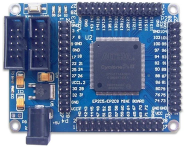
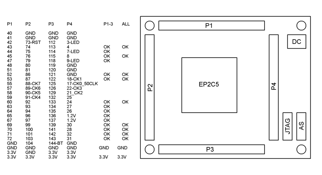
The EP2C5T144 FPGA board is the main board used for most designs. It supports approximately 5K logic units with 13Kbytes of internal memory. The circuit board has four ports for expansion, with port 4 primarily used for interfaces.
Serial I/O Board
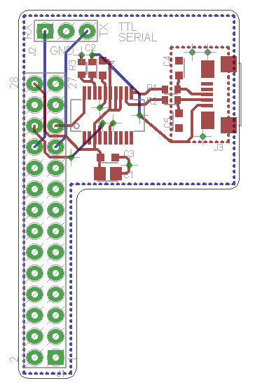
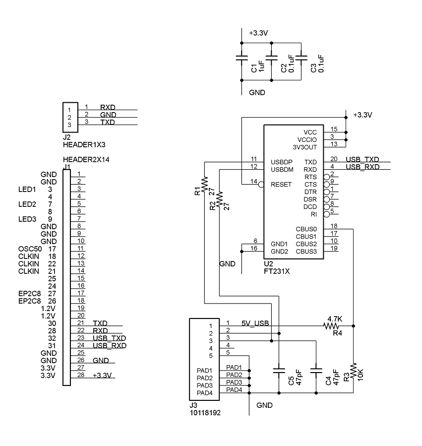
The Serial I/O board can function as a 3.3Vdc TTL serial level or a micro USB interface. The default serial port is set to 115Kbaud, 8 data bits, 1 stop bit, and no parity. When connected to port 4, the pin out is as follows: RX-pin 32 and TX-pin-31.
Ethernet Board
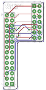
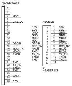
The Ethernet board uses an inexpensive off the shelf Ethernet board with an RM-II interface. The Ethernet circuit card is based on the Microchip LAN8720 integrated circuit. The Ethernet examples on this website use the 100Mbit speed.
Switch, LED and PWM Board
The board includes four normally open momentary switches, four red LED’s, four full-color WS2811 LED’s, and three +5V outputs. The 5V outputs can drive standard servo motors or WS2811 LED’s. Ensure that 5Vdc power is applied to the power header for the board to function.
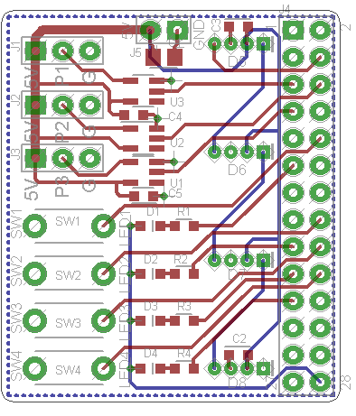
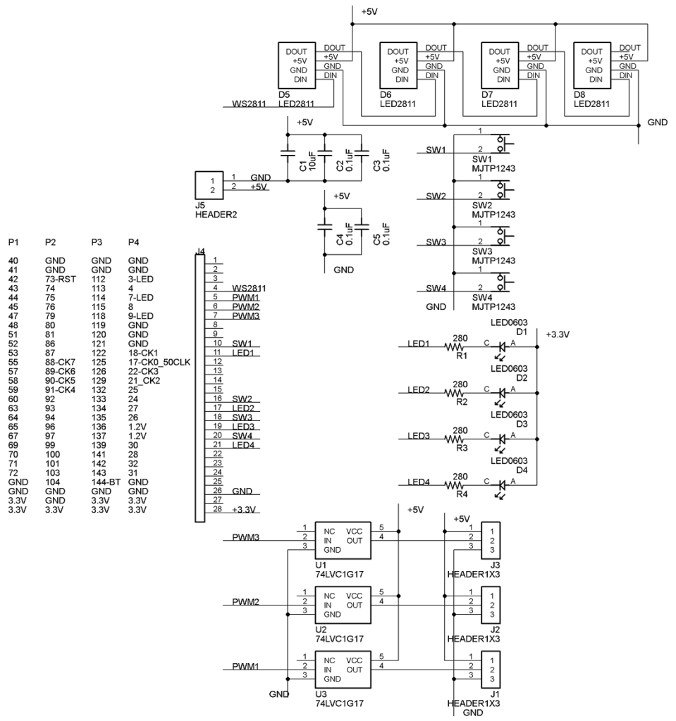
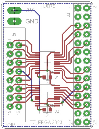
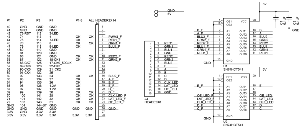
LED matrix HUB75 Board
This board supports one HUB75 connector with both 8 to 1 and 16 to 1 multiplexing.
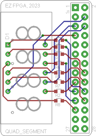
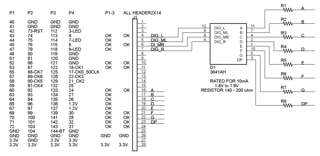
Quad Seven Segment Board
This board demonstrates multiplexing on a four-digit seven-segment display.
